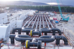
در این مقاله Slug Catcher به عنوان یک تجهیز حیاتی در صنایع نفت و گاز مورد بررسی قرار می گیرد. این تجهیز برای جمع آوری و جداسازی مایعات از گاز در خطوط لوله دوفازی طراحی شده و نقش مهمی در حفظ ایمنی و کارایی تجهیزات پایین دستی ایفا می کند.

مقدمه
در صنایع نفت و گاز، انتقال سیالات در خطوط لوله دوفازی (گاز و مایع) به دلیل تغییرات دینامیکی جریان، چالش های فراوانی ایجاد می کند. یکی از مهم ترین مشکلات، تشکیل “اسلاگ” یا توده های مایع بزرگ در خطوط لوله است که می تواند باعث ایجاد نوسانات فشار و اختلال در فرآیندهای تولیدی شود. این وضعیت می تواند به کاهش بازده تولید، آسیب به تجهیزات پایین دستی، و افزایش هزینه های نگهداری منجر شود. برای مقابله با این مشکل، از تجهیزاتی به نام “Slug Catcher” استفاده می شود.
“Slug Catcher” به گونه ای طراحی شده است که بتواند حجم زیادی از مایعات را که به صورت ناگهانی وارد خط لوله می شوند، بدون ایجاد اختلال در جریان گاز، دریافت و ذخیره کند. این تجهیز با توجه به نوع جریان، محیط عملیاتی و نیازهای خاص هر پروژه، در انواع مختلفی از جمله نوع ظرفی و نوع چندلوله ای ساخته می شود. نوع چندلوله ای که به دلیل سادگی در طراحی و قابلیت تحمل فشارهای بالا بیشتر در خطوط لوله با قطر بزرگ استفاده می شود، یک انتخاب مرسوم برای پروژه های بزرگ و پیچیده است.
طراحی و ابعاد Slug Catcher باید به گونه ای باشد که بتواند حداکثر حجم مایع ممکن را در شرایط مختلف عملیاتی مدیریت کند. از آنجایی که شرایط عملیاتی خطوط لوله و پروفیل جریان به طور مداوم تغییر می کند، استفاده از شبیه سازی های کامپیوتری و روش های محاسباتی پیشرفته برای طراحی دقیق این تجهیزات ضروری است. Slug Catcher نه تنها به عنوان یک واحد جمع آوری و جداسازی مایع عمل می کند، بلکه نقش کلیدی در افزایش عمر مفید تجهیزات و بهبود کارایی کلی سیستم های فرآوری گاز دارد.
Table of Contents
Chapter 1 Introduction. 6
Introduction. 7
Chapter 2 Slugs. 10
Slugs: 11
Chapter 3 Slug Catcher Tool 12
3.1 Slug Catcher. 13
3.1.1 Performance ……………………………….13
3.1.2 How it works. 13
3.1.3 Standard Features……………………………………..13
3.2 Purpose of Slug Catcher. 15
Chapter 4 Slug Catcher Design. 16
4.1 Slug Catcher Design. 17
4.2 General design aspects of multiple-pipe slug catcher. 17
4.3 Condition of liquid to be separated in slug catcher. 25
4.4 A new approach for sizing finger-type (multiple-pipe) slug catchers. 25
4.5 Case study: Slug catcher sizing in South Pars phases 22, 23 and 24. 38
4.6 Example of Slug Catcher model 41
4.7 Computer Simulation……………………………..44
References: 46
Abstract
A two phase flow pipeline is intended for transporting the gas and liquid phases simultaneously. There are different modesunder which liquid can be produced from the pipeline.These include : the continuous liquid flow production mode under normal steady flow conditions; the intermittent or transient liquid production mode occurring when flow rates are varied and the pigging or sphering mode when liquid is displaced within the pipeline in a relatively short time. These occasionally very large volumes of liquids encountered must be handled and stored as they emerge from the pipeline, preferably without any reduction in velocity, which would be reflected in the gas production. For this reason, a liquid receiving facility known as slug catcher is always connected to a two phase pipeline
Introduction
A two-phase flow pipeline is intended for transporting the gas and liquid phasessimultaneously. There are different modes under which liquid can be produced from the pipeline. These include: the continuous liquid flow production mode under normal steady flow conditions; the intermittent or transient liquid production mode occurring when flow rates are varied (Severe Slugging in Figure1); and the pigging or sphering mode when liquid is displaced from the pipeline into the slug catcher in a relatively short time. These occasionally very large volumes of liquids encountered must be handled and stored as they emerge from the pipeline, preferably without any reduction in velocity, which would be reflected in the gas production. For this reason, a liquid-receiving facility known as a slug catcher is always connected to a two-phase pipeline. In the past ten years, the range of application of two-phase pipeline transportation has broadened considerably. Conditions under which slug catchers are required to operate have extended to higher flowrates involving also mist and droplet flow conditions for which more stringent separation requirements have become necessary and in some cases very large liquid quantities have to be handled. This paper has combined existing design approaches with results based on an additional investigation of liquid separation under high velocity conditions so that the revised design requirements can be met.
There are basically two types of slug catchers, the vessel and multiple-pipe types;multiple-pipe separators have been widely applied in facilities processing a gas condensate stream. For crude-oil stream, where foaming sometimes emerges as a major problem, a vessel type slug catcher is normally used. Such a slug-catching separator must be designed to process the incoming liquid slugs produced by normal pipeline slug flow and to perform an adequate initial separation of the gas and liquid phases. The geometry of the vessel type slug catcher could range from a simple “knock out drum” to a more sophisticated layout. Since the overall length of vessel type slug catchers is relatively short for a given volume this type is preferred in the case of limited plot sizes (e.g. offshore platforms). For larger liquid volumes accommodation (More than 100 m3) multiple-pipe slug catcher should be used.
فایل این مقاله به زبان انگلیسی می باشد.
![]() فرمت فایل: WORD
فرمت فایل: WORD
![]() تعداد صفحات: 20
تعداد صفحات: 20
مطالب مرتبط
